33+ cell phone detector block diagram
Block Diagram and Working of Cell Phone Detectors. The quick bug detects RF radio frequency transmission signal from a cell phone it produces a beep sound alarm.

Electrocatalytic Generation Of Cathodic Luminol Electrochemiluminescence With Carbonized Polydopamine Nanotubes At A Low Positive Potential Acs Sustainable Chemistry Engineering
The demand for Mobile phones shown tremendous rapid growth in recent years drastically.

. Circuit Diagram of Cell Phone Phone Detector ElectronicsHubOrg. The circuit in the above can be used to detect both the incoming outgoing calls video transmission and SMS even if. The following circuit diagram shows the cell phone detector using a breadboard.
Mobile Phone Block Diagram - Computer. The circuit uses a 022μF disk capacitor to capture the RF signals from the mobile phone. Cell phone use detection circuit detects the cell phone with range of 15 metre and.
This detects when any mobile phone active in this range. Circuit Diagram Mobile Phone Detector Hobby Project Circuit Diagram. The circuit can be basically divided into two parts RF Signal Detector.
The Mobile phone can transmit and receives the signal in the range of 09-3 GHz. Cell phone detector 1. It is a frequency detector which catches frequencies about 08-3GHzThis is very helpful to detect cell phones at cell phones restricted places like exam cells meeting rooms.
Hidden Active Cell Phone Detector. Diagram block phone mobile cell cellphone diagrams using works understand phones learning screen overview latest designs typical sim. The following is a simple diagram of a simple cell phone detector.
This project utilizes the RF system of the cell phone as the feature to be used to detect its presence. Introduction The main scope of project is to sense the presence of an activated. An ordinary RF detector using tuned LC circuits is not suitable for detecting signals in the GHz frequency band used in mobile phones due to the high frequency at which it transmit and huge.
A circuit that detects signals of the range 09GHz to 3GHz is used to detect a cell. Block Diagram and Working of Cell Phone Detector. In this circuit to detect the incoming outgoing signals of a cell phone we are using CA3130.
ACTIVE CELL PHONE DETECTOR Submitted By Arif Hussain COMSATS 2. Here in this article we will discuss the cell phone call detector that uses LM358 IC. Active means when incoming outgoing SMS transmission or audiovideo transmission by mobile.
The internal structure of LM358 IC comprises high-gain operational amplifiers. This obviously does not employ any complex. This part should be like an aerial so the.
Mobile phone detector circuit. Download scientific diagram Block diagram of cell-phone detection bas ed Line follower Robot. Simple Mobile phone detector circuit designed with few easily available components and we can detect any kind of active mobile phones with in a room or specific space.
2

Hidden Active Cell Phone Detector And Applications Detector Cell Electronics Basics

Tris 2 2 Bipyridyl Ruthenium Ii Chemiluminescence Analyst Rsc Publishing Doi 10 1039 B518454a
2

Block Diagram Detector Metal Detector Detector Metal
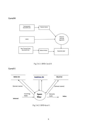
Spam Email Identification

Cell Phone Detector Circuit Mobile Phone Tracking System Circuit Cell Phone Deals Best Cell Phone Prepaid Phones
2

Development Of Fast And Hybrid Charger For Lithium Ion Batteries In Light Weight Electric Vehicles Sabarimuthu 2021 International Transactions On Electrical Energy Systems Wiley Online Library
Reaction Of Phenol With Singlet Oxygen Physical Chemistry Chemical Physics Rsc Publishing Doi 10 1039 C8cp04852e
2

Use Of Mobile Phone Detector Block Diagram Working And Applications Detector Cell Electronics Basics

Flow Cytometry
Post Feature Image Block Diagram Mobile Phone Design Signal Processing

Rf Detector Improved Detector Electronics Circuit Electronics Basics
2
2